English
 Spanish
 Russian
 Arabic
 Portuguese
 Korean
 Turkish
 Hindi
Hindi Indonesia
 Thai
ThaiStructure and Working Principle of Rotor Spinning Machine
The main difference between rotor spinning and other free-end spinning is that the coagulation and twisting mechanism and function are different. After the single fiber enters the rotor, it is first sent to the inclined surface of the inner wall of the rotor. The condensing and twisting mechanism of the rotor spinning machine is mainly composed of rotors, twist resistance heads and other parts. In order to spin yarns of various thicknesses, it is necessary to select rotors and condensing grooves with different diameters and groove shapes. The inner wall of the spinning rotor is called the slip surface, and the largest diameter is the coagulation trough. The centrifugal force generated by the high-speed rotation of the spinning rotor plays the role of agglomerating fibers, so it is also called the inner centrifugal spinning rotor.
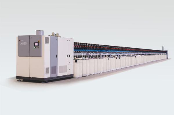
Rotor Spinning Machine

JGR232 Rotor spinning machine is one of the similar type of positioning is higher, the design of fast new spinning equipment, the product structure design is reasonable, install the tray type spinning box, using high quality spare parts at home and abroad, its optimal spinning range is wide, the main raw material for: pure cotton, pure polyester, polyester/cotton, viscose, recycle, lint cotton and blended, etc...
Structure and working principle of rotor spinning machine
The principle of rotor spinning is to generate centrifugal force in the rotor through the high-speed operation of the rotor.
The input sliver is first opened and drafted by the opening roller. The fibres are transported via a tube to the rotor where the fibre strand is subjected to twist insertion. After twisting, the output yarn is then wound into ‘cheese’ or ‘cone’ packages of the required size. The input sliver can be a carded or drawn sliver. Generally, a drawn sliver is used. The sliver is pulled through a condenser by a feed roller, operating in conjunction with a spring-loaded feed pedal. The nip point between feed roller and feed pedal determines the position of fibre bundles moving into the opening roller.
A sliver may have more than 20,000 fibres in its cross-section. This means that a yarn of 100 fibres in a cross-section will require a total draft of 200.
This amount of draft is substantially higher than that in ring spinning. Drafting in rotor spinning is accomplished first using an opening roller (mechanical draft) which opens the input sliver, followed by an air stream (air draft).
The rapidly rotating opening roller combs out the leading ends of fibres. The separated trash is collected in a central chamber from where it can be removed. The fibre from the opening roller is sucked through a transport tube and deposited into the inner grooved surface of the rotor.
The transport tube is tapered so as to create an accelerating air stream, which straightens the fibres. These two operations produce an amount of draft that is high enough to reduce the 20,000 fibres entering the opening roll down to few fibres (2–10 fibres) at the exit of the transport tube.
Consolidation in rotor spinning is achieved by mechanical twisting. The torque generating the twist in the yarn is applied by the rotation of the rotor.
The amount of twist (turns per metre) is determined by the ratio between the rotor speed (rpm) and the take-up speed (metres/min). Every turn of the rotor produces a turn of twist. The winding operation in the rotor spinning is completely separate from the drafting and the twisting operations.